Showing posts with label LED. Show all posts

Using Laser Torch Intruder Detector Circuit Diagram

This is the Using Laser Torch Intruder Detector Circuit Diagram. intruder detector that uses an invisible laser beam to detect the intruder. The laser beam is produced using a 3V DC or 4.5V DC laser pointer or torch that is available in the market. The 3V DC or 4.5V DC power supply for the laser transmitter can also be given using a Bridger rectifier or full-wave rectifier.

Fig. 1 shows the block diagram of the complete unit comprising the transmitter and receiver sections. The laser beam from the transmitter after reflection from various mirrors (M1 through M6, as shown in Fig. 1) is made to fall on the photo detector in the receiver circuit.

Using Laser Torch Intruder Detector Circuit Diagram 1
 Fig. 1: Block diagram of intruder detector using laser torch

Once the laser beam is positioned, the receiver circuit is powered by closing switch S. An alarm unit operating on 230V AC is connected to the relay RL in the receiver circuit.

When an intruder interrupts the path of the beam or switches off the laser torch, the alarm unit becomes activated. The alarm unit remains activated until reset switch S is opened. To activate the alarm circuit again, reset switch S should be closed. The total distance traveled by the laser beam should be less than 800 m for 4.5V laser torch and 500 m for 3V laser torch.

The circuit of the receiver is shown in Fig. 2. When reset switch S is closed, the circuit is powered on. As the laser beam falls on the photo detector, transistor T (BC547) conducts, resulting in the collector being pulled down to ground potential. Thus no current flows to the gate of the SCR and it remains off.
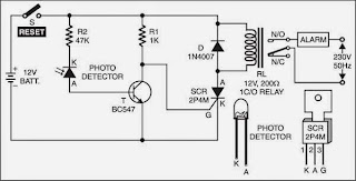
Using Laser Torch Intruder Detector Circuit Diagram

Fig. 2: Receiver circuit

Once the path of the laser beam is interrupted, the base current of the transistor becomes very low and the transistor is driven to cut-off. Now the current starts to flow through resistor R1 and to the gate of SCR. Hence the SCR is fired and it begins to conduct. Thus relay RL connected to the anode of SCR is switched on and the alarm is activated. The alarm sounds until reset switch S is opened to turn off power to the circuit.

EFY Lab note:  We tested the circuit using only one mirror and found its range to be 25-30 metres. The range depends on the intensity of laser beam falling on the photodetector.
Author : G. Susinder Rajan
Read More

LBL Activated Remote Control Circuit Diagram

This is the simple Laser Beam Light Activated Remote Control Circuit Diagram. The following post illustrates a simple light toggled/operated remote control circuit, which can be activated by an ordinary flashlight or more effectively through a laser beam unit (key chain type).

 LBL Activated Remote Control Circuit Diagram


The circuit idea may be understood with the below mentioned points:

  1. Transistor T1 alnog with R3, C6 and the LDR itself forms a simple light sensor stage.
  2. The LDR is connected across the base of the transistor and the positive supply such that when light falls over the LDR, T1 receives the required base bias and conducts.
  3. When T1 conducts, the high potential at pin 14 of IC1 is pulled to logic low. However since a logic low wouldn't effect pin#14, IC1 does not respond as yet.
  4. The moment light on the LDR is switched OFF, T1 is switched OFF and pin#14 now instantly receives a subsequent logic high via R5.....now IC1 responds, and shifts it's output from pin#3 to pin#2. This makes pin#3 logic low, activating T2, and the preceding relay driver stage.
  5. The above condition persists until the LDR is illuminated again with a flashlight or with a laser beam.
  6. The above operation alternately toggles the output ON and OFF providing the required toggling actions to the connected load.
  7. The LDR must be covered inside an opaque pipe, about an inch long so that the ambient light stays obstructed from the LDR.
  8. The angle of the pipe should be kept in a such a way that it facilitates easy focusing of the light beam toward the LDR.
  9. C6 ensures that the system does not respond to accidental spurious light beams in case it finds its way inside the pipe, and over the LDR.

Parts List

  • R3,R4,R5,R6,R7 = 2K2
  • T1 = BC547,
  • T2 = BC557
  • IC1 = 4017
  • IC2 = 7812
  • ALL DIODES = 1N4007
  • C6,C7 = 10uF/25V
  • C8 = 1000uF/25V
  • C10 = 0.1uF
Read More

(LED) 230 V Flasher Circuit diagram

This circuit operates with 230v.you can use this circuit to decorate your parties.I think this will be a wonderful circuit to you all.This circuit was taken from my old circuit book called 100 circuit book.Here DIAC ER 900 and Triac BTW 11-400.

230 V Flasher Circuit diagram


Note:
  • Be careful when you deal with 230V
  • Build this circuit on a PCB
  • Use only mentioned values. 


Read More

Build a Flashing Light with Twilight Switch Circuit Diagram

Build a Flashing Light with Twilight Switch Circuit Diagram. Flashing light is very useful in order to indicate any obstruction or working in progress. The project automatic flashing light with twilight switch flash light in dark but during day it automatically turns off itself.

The circuit diagram of automatic flashing light with twilight switch is shown below where LDR is used as sensor. In the presence of light LDR offer low resistance and in dark it offers high resistance. When there is absence light, LDR offer high resistances which turn off the transistor T1. Due to this darlington pair made from transistor T2 and T3 is turn on which further glow bulb. The feedback from its output is given to the junction of resistor R2 and LDR as shown in circuit diagram. Due to feedback this circuit works as oscillator which work as flasher. Variable resistor VR1 is used to adjust the sensitivity of LDR.

Flashing Light with Twilight Switch Circuit Diagram


PARTS LIST
Resistors (all ¼-watt, ± 5% Carbon unless stated otherwise)
R1 = 2.2 KΩ
R2, R3 = 1 KΩ
R4 = 3.3 KΩ
VR1 = 25 KΩ
Capacitors
C1 = 1 µF – 10 µF
Semiconductors
T1, T2 = BC547B
T3 = BEL187-P
Miscellaneous
LDR
B1 = 3V to 10V bulb
Read More

MAX231 RS-232C LED Circuit Diagram

This is the simple MAX231 RS-232C LED Circuit Diagram. Use a pair of Maxim`s 5V-powered MAX231 RS-232C transmitters as drivers to obtain a 2-color LED. The transmitters require only a singleended, 5-V input to generate ± 10 V internally.

MAX231 RS-232C LED Circuit Diagram

MAX231 RS-232C LED Circuit Diagram
Their outputs are short-circuit-proof and can supply as much as 10 mA-enough to drive most LEDs. Depending on which LED you select, their currentlimiting feature might also eliminate the need for external series resistors.


Read More

LED lamp with integrated radar can monitor the state of health of the elderly

LED lamp with integrated radar can monitor the state of health of the elderly
 
 
The Japanese company unveiled Union Tool LED lamp with a built 24 GHz millimeter wave radar, which was developed by a division of the system LSI Corporation Panasonic. The technology, called Laser Light, illuminates the room as a standard bulb while tracking everything that happens in the room.

Miniature radar, built-in Laser Light, captures objects in front of him at a distance of up to 8 m. The viewing angle is 160 °. Thus, the lamp attached to the ceiling at a height of 3 m from the floor, covering his "look" space equal in size to eight tatami (about 13.2 square meters). It can track the movements of several people in sight, and record unusual situations (for example, if someone tripped and fell).

Radar Panasonic consists of a receiver and transmitter integrated into a single CMOS chip. The device can be operated in continuous wave mode with frequency modulation, very accurately measure the distance to a given object. With this lamp Laser Light has a number of interesting possibilities. For example, being on the ceiling above the bed, it can capture the rhythm of breathing or sleep lying on her person.

Sales of Laser Light will begin in September 2015 the main buyers of the product may make hospitals and nursing homes. Already in the first year, the company expects to bring the Union Tool sales Laser Light fixtures up to 300 million yen ($ 2.6 million).  Link
Read More

LED Flashlight Using Supercapacitor

Bored of joking with capacitors? Then its time for you to maneuver on to super-capacitors. These have huge storage capabilities. during this article you may conclude the way to build atiny low LED flashlight using supercapacitors.

The most disadvantage of capacitors is their giant voltage drop. For this project, a minimum voltage of two volts is needed to light-weight the LED. As a result, the “Joule Thief” style would be incorporated here. Using this, a AA battery is used to light-weight an LED until it's fully discharged.
 during this case, a supercapacitor would be taking the place of the battery. Here an LED is employed to perform the operate of a diode. This ensures that there's sufficient voltage across the LED.

 the necessities of the project are listed below:
White LED
Super capacitor (10F, 2.7 V)
Transistor
Torus
1 k ohm resistor
Wires
Breadboard
The torus and therefore the transistor used here comes from an energy-saving lamp HS. Care ought to be taken whereas removing this from the lamp as a breakage may lead to the discharge of the mercury vapors. A lamp load along side a USB port is added to the circuit. This makes it compatible with a computer or a automotive radio.


A couple of precautions got to be taken whereas constructing the circuit. The USB port mustn't be supplied with excess power. The capacitor doesn't stand up to a high voltage and hence a zener diode is connected in parallel to handle the high voltage. The diode protects the capacitor when the voltage exceeds an explicit price.
Read More

LED light-weight Box

For beginners, it's their 1st project that offers them a lift. And so as to induce that, it's continuously necessary to create positive that the project that you just choose is basically helpful. One such project is that the RGB light-weight fader. this is often quite straightforward and may be done simply by a beginner. scan on to understand a lot of concerning this.


 Concerning twenty LEDs are needed here. begin by wiring all the LEDs and connecting it to a breadboard. this is often quite a tedious method and takes quite plenty of your time.

 ensuing step is to create the ability board. Quite plenty needs to be done to drive all the LEDs employing a single PWM channel. therefore to atone for this, a multiplexer IC is employed. a couple of voltage conversions is also needed in such a case.


 As mentioned earlier, one PWM is employed to regulate 3 totally different channels. The MSP430 is employed to modify between the various channels. this offers the impression that there are 3 individual channels. There is also some problems with the glint, however this might not be a show stopper downside.

 The supply code for running the circuit is kind of sophisticated . concerning twelve totally different modes are gift here and switching between the assorted modes is finished employing a single push button.
Read More

40 LED Bicycle Light Circuit Diagram

The 555 circuit below is a flashing bicycle light powered with four C,D or AA cells (6 volts). Two sets of 20 LEDs will alternately flash at approximately 4.7 cycles per second using RC values shown (4.7K for R1, 150K for R2 and a 1uF capacitor). Time intervals for the two lamps are about 107 milliseconds (T1, upper LEDs) and 104 milliseconds (T2 lower LEDs). Two transistors are used to provide additional current beyond the 200 mA limit of the 555 timer. A single LED is placed in series with the base of the PNP transistor so that the lower 20 LEDs turn off when the 555 output goes high during the T1 time interval. The high output level of the 555 timer is 1.7 volts less than the supply voltage.

Circuit  Project: 40 LED Bicycle Light

Adding the LED increases the forward voltage required for the PNP transistor to about 2.7 volts so that the 1.7 volt difference from supply to the output is insufficient to turn on the transistor. Each LED is supplied with about 20mA of current for a total of 220mA. The circuit should work with additional LEDs up to about 40 for each group, or 81 total. The circuit will also work with fewer LEDs so it could be assembled and tested with just 5 LEDs (two groups of two plus one) before adding the others.
Read More

Police Lights associate crystal rectifier Project

This circuit uses a 555 timer that is setup to each runn in associate Astable operative mode. This generates a nonstop output via Pin three within the type of a sq. wave. once the timer's output changes to a high state this triggers the a cycle the 4017 4017 decade counter telling it to output consecutive sequent output high. The outputs of the 4017 ar connected to the LEDs turning them on and off.

Schematic
Police Lights and LED Project

Parts List

1x - NE555 Bipolar Timer
1x - 4017 Decoded Decade
6x - 1N4148 Diode
1x - 1K Resistor (1/4W)
1x - 22K Resistor (1/4W)
2x - 4.7K Resistor (1/4W)
6x - 470 Resistor (1/4W)
1x - 2.2µF Electrolytic Capacitor (16V)
2x - BC547 NPN Transistor
2x - LED (Blue)
2x - LED (Red)
1x - 9V Voltage Battery 
Read More

Quick Draw Circuit Diagram

The object of Quick Draw is to test your reaction time against your opponent's. A third person acts as a referee and begins the duel by pressing S1, which lights LED1. Upon seeing LED1 go on, you try to outdraw your opponent by moving S2 from "Holster" position to "Draw" position before your opponent moves S3 from "Holster" to "Draw" position. Who ever gets there first will light the corresponding LED and will automatically prevent the other LED from lighting, clearly indicating a winner.


 Quick Draw Circuit Diagram


Quick Draw Circuit


Source:www.home.maine.rr.com
Read More

LED Christmas Star Circuit Diagram

This circuit can be used to construct an attractive Christmas Star. When we switch on this circuit, the brightness of lamp L1 gradually increases. When it reaches the maximum brightness level, the brightness starts decreasing gradually. And when it reaches the minimum brightness level, it again increases automatically. This cycle repeats. The increase and decrease of brightness of bulb L1 depends on the charging and discharging of capacitor C3. When the output of IC1 is high, capacitor C3 starts discharging and consequently the brightness of lamp L1 decreases. IC2 is an opto-isolator whereas IC1 is configured as an astable multivibrator. The frequency of IC1 can be changed by varying the value of resistor R2 or the value of capacitor C1.

LED Christmas Star


Remember that when you vary the frequency of IC1, you should also vary the values of resistors R3 and R4 correspondingly for better performance. The minimum brightness level of lamp L1 can be changed by adjusting potentiometer VR1. If the brightness of the lamp L1 does not reach a reasonable brightness level, or if the lamp seems to remain in maximum brightness level (watch for a minute), increase the in-circuit resistance of potmeter VR1. If in-circuit resistance of potmeter VR1 is too high, the lamp may flicker in its minimum brightness region, or the lamp may remain in off state for a long time. In such cases, decrease the resistance of potmeter VR1 till the brightness of lamp L1 smoothly increases and decreases. When supply voltage varies, you have to adjust potmeter VR1 as stated above, for proper performance of the circuit. A triac such as BT136 can be used in place of the SCR in this circuit. Caution: While adjusting potmeter VR1, care should be taken to avoid electrical shock.
Read More

LCD Module in 4-bit Mode Circuit Diagram

In many projects use is made of alphanumeric LCDs that are driven internally by Hitachi’s industry-standard HD44780 controller. These displays can be driven either in 4-bit or 8-bit mode. In the first case only the high nibble (D4 to D7) of the display’s data bus is used. The four unused connections still deserve some closer attention. The data lines can be used as either inputs or outputs for the display. It is well known that an unloaded output is fine, but that a floating high-impedance input can cause problems. So what should you do with the four unused data lines when the display is used in 4-bit mode? This question arose when a circuit was submitted to us where D0-D3 where tied directly to GND (the same applies if it was to +5 V) to stop the problem of floating inputs.

The LCD module was driven directly by a microcontroller, which was on a development board for testing various programs and I/O functions. There was a switch present for turning off the enable of the display when it wasn’t being used, but this could be forgotten during some experiments. When the R/Wline of the display is permanently tied to GND (data only goes from the microcontroller to the display) then the remaining lines can safely be connected to the supply (+ve or GND). In this application however, the R/Wline was also controlled by the microcontroller. When the display is initialised correctly then nothing much should go wrong. The data sheet for the HD44780 is not very clear as to what happens with the low nibble during initialisation.

Circuit diagram :
LCD module_in_4-bit_Mode_Circuit_Diagramw
LCD Module in 4-bit Mode Circuit Diagram

After the power-on reset the display will always be in 8-bit mode. A simple experiment (see the accompanying circuit) reveals that it is safer to use pull-down resistors to GND for the four low data lines. The data lines of the display are configured as outputs in this circuit (R/Wis high) and the ‘enable’ is toggled (which can still happen, even though it is not the intention to communicate with the display). Note that in practice the RS line will also be driven by an I/O pin, and in our circuit the R/W line as well. All data lines become high and it’s not certain if (and if so, for how long) the display can survive with four shorted data lines. The moral of the story is: in 4-bit mode you should always tie D0-D3 via resistors to ground or positive.


Read More

Efficient, Automatic, White LED Emergency Light Circuit

Referring the figure, we see that the circuit is actually very easy to understand, let’s evaluate it with the following points:
The transformer, bridge and the capacitor forms a standard Power supply for the circuit. The circuit is basically made up of a single PNP transistor, which is used as a switch here.
We know that PNP devices are referenced to positive potentials and it acts like ground to them. So connecting a positive supply to the base of a PNP device would mean grounding of its base. Here, as long as mains power is ON, the positive from the supply reaches the base of the transistor, keeping it switched off. Therefore the voltage from the battery is not able to reach the LED bank, keeping it switched off.
In the meantime the battery is charged by the power supply voltage and it’s charged through the system of trickle charging.
However, as soon as the mains power disrupts, the positive at the base of the transistor disappears and it gets forward biased through the 10K resistor.
The transistor switches ON, instantly illuminating the LEDs.
Initially all the diodes are included in the voltage path, and are gradually bypassed one by one as the LED gets dimmer.


Parts List
R1 = 10K,
C1 = 100uF/25V,
D1, D2 = 1N4007,
D3---D6 = 1N5408,
T1 = BD140
Tr1 = 0-9V, 500mA,
LEDs = white, hi-efficiency, 5mm,
S1 = switch with three changeover contacts.
Read More

1.5 volt dual LED flasher Circuit Diagram

This 1.5 volt led fasher runs more than a year on a single 'd" cell and alternately flashes 2 LEDs at about a 1 second rate. The circuit employs a 74HC14 CMOS hex inverter that will operate at very low voltages (less than 1 volt). One section is used as a squarewave oscillator (pins 1 and 2), while the others are wired to produce a short 10mS pulse on alternate edges of the square wave so the LEDs will alternate back and forth. The output sections each use a capacitor charge pump to increase the voltage for the LEDs. 

The circuit draws an average current of 800uA from the 'D' battery and the LED peak current is about 40mA with a fresh battery and drops to about 10mA as the battery voltage falls to 1.1 volts. The capacity of a alkaline 'D' cell is about 12 amp hours with a cutoff voltage of 1.1 so the circuit should run about 12/.0008 = 15000 hours or maybe 625 days, but I haven't verified that yet. The idea for this circuit came from a single 1.5 volt LED flasher by Dave Johnson that can viewed at

1.5 volt dual LED flasher Circuit Diagram


1.5 volt dual LED flasher Circuit Diagram


Author : Bill Bowden 
Read More

Cheap LED flasher Circuit Diagram

Cheap LED flasher Circuit Diagram

This two LED flasher circuit uses any DC supply from 3V to 12V. Flash rate is controlled by R1,C1 and R2,C2. Larger values create slower fash rates, smaller values higher flash rates.
Read More

LED Voltmeter Circuit Diagram

This is a simple LED Voltmeter Circuit Diagram. Four µ741 op-amps are used here to measure the voltage ranging from 3V to 12V DC. The voltage measured is displayed on eight LEDs.

The inverting inputs (pin 2) of IC1 through IC4 are supplied with regulated 12V DC through voltage dividers R1 through R4. So the inverting input of each op-amp forms the reference voltage. The non-inverting inputs (pin 3) of the op-amps are tied together and connected to the input terminals. The voltage to be meaured is fed to these input terminals.

When the input voltage exceeds the reference voltage of any of the op-amps, its output goes high, making the corresponding LEDs to glow.

This circuit is designed to measure 3V, 6V, 9V and 12V DC. For instance, when the input voltage is 3V, LED7 and LED8 glow. When the input voltage is 12V, all the LEDs glow.

Note. You can use a quad device such as LM324 instead of µ741 ICs. 

LED Voltmeter Circuit Diagram

Simple LED Voltmeter


Read More

16 Stage Bi-Directional LED Sequencer Circuit Diagram

The bi-directional sequencer uses a 4 bit binary up/down counter (CD4516) and two "1 of 8 line decoders" (74HC138 or 74HCT138) to generate the popular "Night Rider" display. A Schmitt Trigger oscillator provides the clock signal for the counter and the rate can be adjusted with the 500K pot. Two additional Schmitt Trigger inverters are used as a SET/RESET latch to control the counting direction (up or down). Be sure to use the 74HC14 and not the 74HCT14, the 74HCT14 may not work due to the low TTL input trigger level. When the highest count is reached (1111) the low output at pin 7 sets the latch so that the UP/DOWN input to the counter goes low and causes the counter to begin decrementing. 

When the lowest count is reached (0000) the latch is reset (high) so that the counter will begin incrementing on the next rising clock edge. The three lowest counter bits (Q0, Q1, Q2) are connected to both decoders in parallel and the highest bit Q3 is used to select the appropriate decoder. The circuit can be used to drive 12 volt/25 watt lamps with the addition of two transistors per lamp as shown below in the section below titled "Interfacing 5 volt CMOS to 12 volt loads"

16 Stage Bi-Directional LED Sequencer Circuit Diagram


16 Stage Bi-Directional LED Sequencer Circuit Diagram
Read More

555 Timer - Frequency and Duty Cycle Calculator

Enter values for R1, R2, and C and press the calculate button to solve for positive time interval (T1) and negative time interval (T2). For example, a 10K resistor (R1) and 100K (R2) and 0.1 uF capacitor will produce output time intervals of 7.62 mS positive (T1) and 6.93 mS negative (T2). The frequency will be about 70 Hz. R1 should be greater than 1K and C should be greater than .0005 uF. Scroll down page for basic 555 information (pinout and two basic circuits).

Positive Time Interval (T1) = 0.693 * (R1+R2) * C
Negative Time Interval (T2) = 0.693 * R2 * C
Frequency = 1.44 / ( (R1+R2+R2) * C) 

First introduced by the Signetics Corporation as the SE555/NE555 about 1971.Pin connections and functions: (See schematic below for basic circuits)
Pin 1 (Ground)    - The ground (or common) pin is the most-negative supply potential of the device, which is normally connected to circuit common when operated from positive supply voltages.

Pin 2 (Trigger)   - This pin is the input which causes the output to go high and beginthe timing cycle. Triggering occurs when the trigger input movesfrom a voltage above 2/3 of the supply voltage to a voltage below1/3 of the supply. For example using a 12 volt supply, the triggerinput voltage must start from above 8 volts and move down to avoltage below 4 volts to begin the timing cycle. The action islevel sensitive and the trigger voltage may move very slowly. Toavoid retriggering, the trigger voltage must return to a voltageabove 1/3 of the supply before the end of the timing cycle in themonostable mode. Trigger input current is about 0.5 microamps.
Pin 3 (Output)    - The output pin of the 555 moves to a high level of 1.7 volts less than the supply voltage when the timing cycle begins. The output returns to a low level near 0 at the end of the cycle. Maximum current from the output at either low or high levels is approximately 200 mA.
Pin 4 (Reset):    - A low logic level on this pin resets the timer and returns the output to a low state. It is normally connected to the + supply line if not used.
Pin 5 (Control)   - This pin allows changing the triggering and threshold voltages by applying an external voltage. When the timer is operating in the a stable or oscillating mode, this input could be used to alter or frequency modulate the output. If not in use, it is recommended installing a small capacitor from pin 5 to ground to avoid possible false or erratic triggering from noise effects.
Pin 6 (Threshold) - Pin 6 is used to reset the latch and cause the output to go low.Reset occurs when the voltage on this pin moves from a voltage below 1/3 of the supply to a voltage above 2/3 of the supply.The action is level sensitive and can move slowly similar to the trigger voltage.
Pin 7 (Discharge) - This pin is an open collector output which is in phase with the main output on pin 3 and has similar current sinking capability.
Pin 8 (V +)       - This is the positive supply voltage terminal of the 555 timer IC.Supply-voltage operating range  is +4.5 volts (minimum) to +16volts (maximum).
The pin connections for the 556 which is a dual 555 timer (2 in one package) areshown in table below. For example, the two outputs for the two timers of the 556 areon pins 5 and 9 which correspond to the output pin 3 of the 555. 
555      556 timer #1        timer #2
Ground         1                  7               7 
Trigger        2                  6               8
Output         3                  5               9
Reset          4                  4               10
Control        5                  3               11
Threshold      6                  2               12
Discharge      7                  1               13+ 
Power Vcc    8                  14              14

The schematics below show the two basic circuits for the 555 timer.


Below is a pictorial view of the 555 timer wired as a LED flasher and powered with a 9 volt battery. The LED will turn on during time T1 and off during time T2.


The 555 circuit below is a flashing bicycle light powered with three C or D cells (4.5 volts). The two flashlight lamps will alternately flash at a approximate 1.5 second cycle rate. Using a 4.7K resistor for R1 and a 100K resistor for R2 and a 4.7uF capacitor, the time intervals for the two lamps are 341 milliseconds (T1, upper lamp) and 326 milliseconds (T2 lower lamp). The lamps are driven by transistors to provide additional current beyond the 200 mA limit of the 555 timer. A 2N2905 PNP and a 2N3053 NPN could be used for lamps requiring 500 mA or less. For additional current, a TIP29 NPN and TIP30 PNP could be used up to 1 amp. A PR3 is a 4.5 volt, 500 mA flashlight bulb. Two diodes are placed in series with the PNP transistor base so that the lower lamp turns off when the 555 output goes high during the T1 time interval. The high output level of the 555 timer is 1.7 volts less than the supply voltage. Adding the two diodes increases the forward voltage required for the PNP transistor to about 2.1 volts so that the 1.7 volt difference from supply to the output is not enough to turn on the transistor. You can also use an LED in place of the two diodes as shown in the lower schematic.


Read More

Make an Efficient LED Emergency Light Circuit

The article describes a very simple homemade emergency light circuit that can be used during power failures and outdoors where any other source of power might be unavailable. The circuit uses LEDs instead of incandescent lamp, thus making the unit very power efficient and brighter with its light output. Moreover, the circuit employs a very innovative concept especially devised by me which further enhances the economical feature of the unit.

We know that LEDs require a certain fixed forward voltage drop to become illuminated and it is at this rating when the LED is at it’s best, that is voltages which is around its forward voltage drop facilitates the device to operate in the most efficient way.
As this voltage is increased, the LED starts drawing more current, rather dissipating extra current by getting heated up itself and also through the resistor which also gets heated up in the process of limiting the extra current.
If we could maintain a voltage around an LED near to its rated forward voltage, we could use it more efficiently. That’s exactly what I have tried to fix in the circuit.
Since the battery used here is a 6 volt battery, means this source is a bit higher than the forward voltage of the LEDs used here, which amounts to 3.5 volts. The extra 2.5 volts rise can cause considerable dissipation and loss of power through heat generation.
Therefore I employed a few diodes in series with the supply and made sure that initially when the battery is fully charged; three diodes are effectively switched so as to drop the excess 2.5 volts across the white LEDs (because each diode drop 0.6 volts across itself).
 Now as the voltage of the battery drops, the diodes series are reduced to two and subsequently to one making sure only the desired amount of voltage reaches the LED bank.
In this way the proposed emergency lamp circuit is made highly efficient with its current consumption, and it provides backup for a much longer period of time than what it would do with ordinary connections.
Make an Efficient LED Emergency Light Circuit

Read More