Showing posts with label Ic. Show all posts

The Propeller IC Programming Circuit Diagram

This is The Propeller IC Programming Circuit Diagram. Parallax, well known for its successful Basic Stamp IC, has recently introduced the Propeller: a new microcontroller with a certain difference. It packs no less than eight 32-bit processors (referred to as COGs in Propeller jargon) into a single package with only 40 pins. That design takes genuine simultaneous multiprocessing possible, and the sophisticated internal structure of the device makes it relatively easy to implement video and signal-processing applications. The Propeller can be programmed in assembly language or the high-level Spin language. The processor and the programming tools were developed entirely in-house by Parallax, with the hardware being designed from scratch starting at the transistor level.
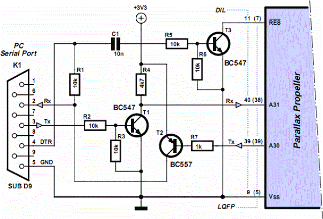
Circuit diagram:

The Propeller IC Programming Circuit Diagram


Programming The Propeller IC Circuit Diagram

The basic idea behind that was to avoid becoming involved in all sorts of patent disputes with other manufacturers. The result is astounding, and for software developers it certainly requires a change in mental gears. As is customary with modern microprocessors, the Propeller has a simple serial programming interface. The developer’s toolkit from Parallax has a modern USB port for that purpose, but a reasonably simple alternative (illustrated here) is also possible for anyone who prefers to work with the familiar RS232 port. Don’t forget that the Propeller works with a 3.3-V supply voltage.

Source by : Streampowers
Read More

Universal PIC Programmer Circuit Diagram

This simple programmer will accept any device that's supported by software (eg, IC-Prog 1.05 by Bonny Gijzen at www.ic-prog.com). The circuit is based in part on the ISP header described in the SILICON CHIP "PIC Testbed" project but also features an external programming voltage supply for laptops and for other situations where the voltage present on the RS232 port is insufficient. This is done using 3-terminal regulators REG1 & REG2. The PIC to be programmed can be mounted on a protoboard. This makes complex socket wiring to support multiple devices unnecessary. 16F84A, 12C509, 16C765 and other devices have all been used successfully with this device.

Circuit diagram:


Simple universal-pic-programmer-circuit-diagramw
Simple Universal PIC Programmer Circuit Diagram


Sourced By : Streampowers
Read More

9 Volt Power Supply Circuit Diagram Using IC 7809

Description
Circuit showing a 9 volt power supply . Here we have used a bridge rectifier and 7809 ic for making this circuit.Where the ic regulate the output to 9 v,1 A .This voltage every time constant.Are you interested ?

Circuit diagram with Parts list. 


Notes. 
  • If a current of 300 mA or above is required, fit a proper heat sink to the IC 7809.
  • If 1A bridge is not available, make one using four 1N 4007 diodes.
Read More

Basic IC MonoStable Multivibrator


Basic LM555 Timer CIRCUIT

Part List
C2 = .01uf
IC1 = LM555 Timer
SWI = n.o. momentary switch
R1 and C1 determine lenght of
out put pulse where  t = R1 x C1
and R1 is in ohms and C1 is in farads .

by Tony van Roon
Read More

LA4440 Stereo Amplifier Circuit Diagram

LA4440 is a dual channel audio amplifier IC. It can be used in two modes; one is Stereo amplifier and another Bridge amplifier mode. The LA4440 is a monolithic linear IC from Sanyo. Here I give the both circuit mode of amplifier using IC LA4440.

When the IC LA4440 is Stereo mode in the circuit, its output power is 6w+6w. In stereo mode use two pieces speaker of 2Ωto8Ω.

 LA4440 Stereo Amplifier Circuit Diagram


LA4440 Stereo Amplifier Circuit Diagram

C10 is filter capacitor used to reduce the ripple of supply voltage. Don’t decrease the value of capacitor C6&C7 less than 100uF, 10v, it may causes of the output at low frequencies goes lower. The pin-6 of LA4440 amplifier circuit  is audio input pin; it used in stereo amplifier mode but in bridge mode it is grounded. C8&C9 are polyester film capacitor used to preventing oscillation, and R1&R2 used for the same reason as filter resistor. Though the maximum supply voltage for both circuit of amplifier is 18V but we recommend to use a 12V,3A power supply. Use a good quality heat sink with LA4440.

I think here you see little comparison between stereo and bridge amplifier of LA4440. If you want to make this amplifier project, then I recommend you the bridge one. I think it is ideal for a beginner. And I love its wattage rather than Stereo mode. There is also a possibilities as I say, make two copies of circuit of bridge amplifier for stereo, it will give you 19w+19w of audio power output.
Read More

LA4440 Bridge Amplifier Circuit Diagram

LA4440 is a dual channel audio amplifier IC. It can be used in two modes; one is Stereo amplifier and another Bridge amplifier mode. The LA4440 is a monolithic linear IC from Sanyo. Here I give the both circuit mode of amplifier using IC LA4440.

When the IC LA4440 is in Bridge mode in the circuit, its output power is 19w. In bridge mode use 4Ω-8Ω speaker. If you want stereo output(19w+19w) in bridge mode then use two copies of amplifier circuit of given below. Resistor R3&R4 is to adjust the voltage gain and for making input signal of inverting amplifier.

LA4440 Bridge Amplifier Circuit Diagram


LA4440 Bridge Amplifier Circuit Diagram


C10 is filter capacitor used to reduce the ripple of supply voltage. Don’t decrease the value of capacitor C6&C7 less than 100uF, 10v, it may causes of the output at low frequencies goes lower. The pin-6 of LA4440 amplifier circuit  is audio input pin; it used in stereo amplifier mode but in bridge mode it is grounded. C8&C9 are polyester film capacitor used to preventing oscillation, and R1&R2 used for the same reason as filter resistor. Though the maximum supply voltage for both circuit of amplifier is 18V but we recommend to use a 12V,3A power supply. Use a good quality heat sink with LA4440.

I think here you see little comparison between stereo and bridge amplifier of LA4440. If you want to make this amplifier project, then I recommend you the bridge one. I think it is ideal for a beginner. And I love its wattage rather than Stereo mode. There is also a possibilities as I say, make two copies of circuit of bridge amplifier for stereo, it will give you 19w+19w of audio power output.
Read More

Compressor Circuit with 570/571 Compandor IC

Compressor Circuit with 570/571 Compandor IC circuit provide high gain for low amplitude input and provide low gain for high amplitude input. This action, in effect, produce a nearly constant amplitude even though the input has very high dynamic range (very high amplitude variation from time to time). The action of compression like this is needed in some situation, such as in maximizing modulation depth in broadcasting, or sustaining electric guitar signal which has very high variation between the plucking time and fading out.  The following circuit has complementary input/output characteristic and unity gain at 0.775 VRMS input. Voltage gain through compressor is square root of 0.7/Vin. Vin is average input voltage. This circuit  uses Signetics dual channel compandor IC.  570 has lower inherent distortion and higher supply voltage range (6-24 V) than 571 (6-18 V).

Compressor Circuit with 570/571 


Build a Compressor Circuit with 570/571 Compandor IC

Read More