How To Build water level controller using an 8051 microcontroller?

 Building a water level controller using an 8051 microcontroller involves using sensors to detect the water level and actuating a pump to control the water level automatically. Here's a step-by-step guide to help you get started with the project:


Components Required:

    • 8051 microcontroller (e.g., AT89C51 or AT89S52)
    • Ultrasonic sensor or water level sensor (e.g., float switch)
    • Motor or water pump
    • Transistors and relays (for interfacing the microcontroller with the motor)
    • Power supply (DC adapter or battery)
    • Resistors, capacitors, and other supporting electronic components
    • Breadboard or PCB for circuit connection
    • Connecting wires

Step-by-Step Guide:

Step 1: Circuit Design

  • Design the circuit on a breadboard or PCB. Connect the 8051 microcontroller, ultrasonic sensor, motor, transistors, and other components according to the schematic.

Step 2: Microcontroller Programming

  • Write the program for the 8051 microcontroller using assembly or C language. The program should read the sensor data and control the motor based on the water level.

Step 3: Sensor Interface

  • Connect the ultrasonic sensor or water level sensor to the appropriate input pins of the microcontroller.
  • Depending on the sensor you choose, you may need additional components like resistors or voltage dividers to interface with the microcontroller.

Step 4: Motor Control

  • Use transistors and relays to interface the microcontroller with the motor. The microcontroller's output pins should drive the transistors, which in turn control the motor's operation.

Step 5: Power Supply

  • Connect a suitable power supply to power the microcontroller and the motor. Ensure that the power supply voltage is compatible with the microcontroller and the motor.

Step 6: Calibration and Testing

  • Calibrate the ultrasonic or water level sensor to accurately measure the water level.
  • Upload the program to the microcontroller and test the water level controller in a controlled environment.

Step 7: Implementing Control Logic

  • In your program, set the desired water level range based on the sensor readings.
  • When the water level goes below the desired range, activate the motor to fill water.
  • When the water level exceeds the desired range, deactivate the motor to stop filling water.

Step 8: Safety Considerations

  • Implement safety measures to avoid overflow or any other potential hazards.
  • Consider adding a low-water level sensor to prevent the motor from running dry.

Step 9: Enclosure

  • Build an enclosure to protect the circuit and components from water and environmental factors.

Step 10: Final Testing and Troubleshooting

  • Test the water level controller in real-world conditions and troubleshoot any issues that may arise.

Remember that this project involves working with electrical components, and safety should be a top priority. Double-check your connections, use appropriate components, and ensure that the circuit and motor are well-isolated from the water to avoid accidents. If you are new to microcontroller projects, it might be helpful to refer to online tutorials and resources for 8051 microcontroller programming and interfacing.

Read More

Tesla shows how it builds ventilators using Model 3 parts

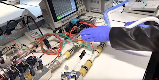
Tesla’s EV plants are shuttered due to the coronavirus, but like other automakers, it’s retooling its operations to build ventilators. Now, the company has released a YouTube video showing a prototype built with EV parts including the Model 3’s display and infotainment system. 


Tesla shows how it builds ventilators using Model 3 parts

Hospital-grade oxygen goes into Tesla’s mixing chamber (a car part used in Tesla’s vehicles). It’s subsequently pumped through Tesla’s custom designed manifold, which is powered by vehicle computers and controlled by the infotainment system. All the patient parameters are then displayed on the Model 3’s main display.

Tesla shows how it builds ventilators using Model 3 parts

First Medtronic units from Tesla getting installed in NY metro area. These are for worst case situations.

Tesla, along with Ford and GM, have promised to donate or build ventilators, and CEO Elon Musk said recently that the New York factory could reopen soon to produce ventilators. The company recently donated 1,000 ventilators, though critics said that the non-invasive models were the wrong kind. That’s because critical COVID-19 patients need invasive ventilators that can inflate a patient’s lungs with air via intubation.

However, New York governor Andrew Cuomo said that the so-called BiPAP non-invasive ventilators could be converted into the right type to help offset the “burn rate” of critical invasive ventilators. Elon Musk subsequently tweeted that “all hospitals were given exact specifications of [the donated models] & all confirmed they would be critical.” He added that Tesla has now started delivering critical intratracheal ventilators from Medtronic for “worst case situations.” Sourced Link
Read More

Automatic Trickle Charger Circuit Diagram

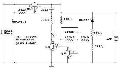
Here is the schematic for the automatic charger I have been using for my kids' battery cars. The charger is a small molded unit that probably doesn't supply more than an amp and this circuit would have trouble with much more. No current limit is provided by this circuit - it relies on the charger for that. The circuit could be modified to provide more current by lowering the 470 and 330 ohm resistors in the 5195's base circuit and the 10k in the collector of the 4401. A relay could also be used in place of the pass transistor.

Automatic Trickle Charger Circuit Diagram

Automatic Trickle Charger Circuit Diagram


Here is how it works: When the battery voltage is low, the voltage at the base of the first 2N4401 (on the right) is not sufficient to turn it on and the second 2N4401 is biased on by the 10k resistor. The power transistor is turned on and the LED lights. When the battery is fully charged the voltage will exceed a somewhat arbitrary "over-voltage" value slightly below 14 volts and the regulator will switch off. The 470k feedback resistor gives the circuit some hysteresis so that it will not turn back on until the battery voltage drops below about 13.5 volts. When the battery is nearing full charge the light will begin to flash on and off and after a few hours the light will only come on occasionally. This occasional over-voltage jolt sure seems to keep the batteries in great shape.
Read More

who finally gets the crown? PlayStation 5 vs Xbox

Less than 48 hours after the release of the official specs of the Microsoft Xbox Series X, Sony also officially announced the specs of PlayStation 5. In all honesty, looking at the specs of these consoles, it’s quite difficult to point out a clear cut winner. The table below lists all the important points of these consoles.


PlayStation 5 vs Xbox Series X – CPU

Now, let us look at the specs of these consoles. For the CPU, the PlayStation 5 comes with an 8-core Zen2 chip with a frequency of 3.5GHz. However, the Microsoft Xbox Series X also uses an 8-core Zen2 chip, but with a frequency of 3.8GHz.

PlayStation 5 vs Xbox Series X – GPU

In terms of GPUs,  PS5 uses 36 sets of CU units and an RDNA2 architecture. This number is much less than XSX which has 52 sets of CU units. However, the core frequency of the GPU of the PS5 is extremely fast, reaching 2.23GHz while the XSX is only 1.825GHz. The floating-point performance of the two is 10.28TFLOPS and 12TFLOPS respectively.

As for such a high frequency, will it reduce during operation? Yes, it will. Nevertheless, Sony claims that in the worst case, a 10% reduction in power consumption will only reduce the frequency slightly, without much impact. Sony said at the press conference that the CPU and GPU frequencies actually change dynamically.

PlayStation 5 vs Xbox Series X – Memory

The PS5’s memory is 16GB GDDR6, 256bit wide and 448GB / s. Although Microsoft XSX is also 16GB GDDR6, it is divided into 10GB and 6GB. The former has a bandwidth of 560GB / s. while the latter is 336GB / s.

For the hard disk, the PS5 y a PCIe 4.0 hard disk, with a performance of 5.5GB / s and compressed data of 8-9GB / s, which is stronger than the 2.4GB / s XSX host. However, in terms of capacity, the PS5 is 825GB and the XSX is 1TB.

In terms of expansion, the PS5 also supports USB mobile hard drives and 4K Blu-ray drives. These two points are the same as XSX, but there is no XSX dedicated expansion SSD. Sony’s view is different from Microsoft’s and does not engage in a dedicated interface.
PlayStation 5 vs Xbox Series X – other aspects

In other respects, the PS5/XSX will also support 8K and 4K 120Hz games. It will also be backward compatible with PS4 games. However, XSX will be backward compatible with

This is the side by side comparison between the PlayStation 5 and the Microsoft Xbox Series X. Now you be the judge. Who is the winner? Let us know your thought in the comment section below


Source :
Read More

Simple Automatic Anchor Light Circuit Diagram

This is a Simple Automatic Anchor Light Circuit Diagram.Most of the cruisers do not use a masthead anchor light because the light is too high above the water level and actually makes it difficult to judge the position of the boat from just the anchor light, especially in a pitch-dark anchorage. That is why many people have devised their own forms of anchor lights that they stick lower to the deck on both sides of their boat.
Here is the circuit of a compact yet inexpensive automatic anchor light integrated with an ambient light sensor that turns it on and off automatically. This 12-volt LED light can be used as a traditional masthead anchor light and/or as an optional pretty clever custom-built anchor light. A typical commercial anchor light is shown in Fig. 2.
The circuit described here (refer Fig. 3) lets you control an electromagnetic relay so that it turns on a white LED light when the preset light level is reached and turns it off when a different preset level is reached. The circuit is built around NE555 IC (IC1). The 5mm light dependent resistor (LDR1) in the circuit triggers the 12V electromagnetic relay (RL1) as per the ambient light level. RL1 drives the 10mm white LED light source (LED2). Series resistor (R2) is included to limit the white LED current.
Automatic Anchor Light Circuit Diagram
 Fig. 3: Circuit diagram of the anchor light
Note that switching threshold is determined by a 470k potentiometer (VR1) that causes the output to toggle with the preset threshold values. The light source (LED2) automatically switches on when it gets dark and switches off when there is sufficient ambient light. The 100µF capacitor (C1) provides a bit of hysteresis to prevent the circuit from jittering near the threshold level. The circuit is optimised for use with a nominal DC voltage of 12V drawn from any standard accumulator commonly used in boats.
Construction and testing
A single-side PCB pattern for the anchor light circuit is shown in Fig. 4 and its component layout in Fig. 5.
PCB pattern of the anchor light circuit

Fig. 4: PCB pattern of the anchor light circuit

Component layout of the PCB
Fig. 5: Component layout of the PCB
The circuit assembled on the small PCB can fit easily inside most prototype/custom enclosures, which should be waterproof for mounting on the masthead.
Suggested enclosure layout
 Fig. 6: Suggested enclosure layout
 If possible, try to add some optics (lens and reflector) with the white LED (LED2) to spread the light outward. The 12V power supply input wires can then be connected to corresponding wires extending from the existing electric-points of the anchor light. Fig. 6 shows how the prototype may be assembled. Author’s prototype is shown in Fig. 7.
 Author’s prototype
 Fig. 7: Author’s prototype
 
Read More