Showing posts with label Amplifier. Show all posts

Simpler Hi-Fi Audio Amplifier Circuit Diagram

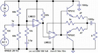
Here are Simpler Hi-Fi Audio Amplifier Circuit Diagram, If  you can settle for more distortion (from about 0.2% to 0.4% at full power) and about 2.5 watts into 8 ohms with a 20 to 24 VDC power supply, the following circuit is a lot simpler. The op-amp has to discharge the base of one transistor to turn it off while also trying to pump charge into the other transistor to turn it on, hence more distortion at crossover. The distortion isn't noticeable for many applications but it's significantly higher than the circuit above. I used a larger, 2200 uF capacitor across the power. If you experience instability try adding a few hundred pF capacitor to the second op-amp from the negative input to the output. This "local" feedback should keep the op-amp happy but it might increase distortion slightly. The circuit will run on lower power supply voltage but at some point you might want to switch to a 4 ohm speaker for more volume. Applications: loud intercom, sound effects, megaphone, signal generator booster, bench amp, etc.

Simpler Hi-Fi Audio Amplifier Circuit Diagram


The NPN heat sink has mica underneath since the top layer is ground. The collector lead passes through a hole to the other side which is Vcc. The collector leads hold the transistor on one end and blobs of epoxy hold the heat sink on the other end. The holes that the various leads pass through have countersinks made by hand with a large drill to prevent shorting; you can see a blue resistor top-left in the picture is passing through to Vcc - that's the top 68k bias resistor. Also see pin 8 of the op-amp passing through to Vcc. I used a socket with long "wire-wrap" legs.

Select high gain transistors and quick op-amps that can deliver high output current to achieve the most output power. A limiting factor can be insufficient drive to the transistors for maximum output power. The transistors will be delivering over an amp at the peaks and some op-amps can't deliver as much current near the rails.
Read More

Simple Crystal Radio Audio Amplifier Circuit Diagram

This is a simple audio amplifier using a TL431 shunt regulator. The amplifier will provide room-filling volume from an ordinary crystal radio outfitted with a long-wire antenna and good ground. The circuitry is similar in complexity to a simple one-transistor radio but the performance is far superior. The TL431 is available in a TO-92 package and it looks like an ordinary transistor so your hobbyist friends will be impressed by the volume you are getting with only one transistor! 
 
 Simple Crystal Radio Audio Amplifier Circuit Diagram
 
Simple Crystal Radio Audio Amplifier Circuit Diagram
 
 
The amplifier may be used for other projects, too. Higher impedance headphones and speakers may also be used. An earphone from an old telephone will give ear-splitting volume and great sensitivity! The 68 ohm resistor may be increased to several hundred ohms when using high impedance earphones to save battery power.

To use the circuit as a general-purpose amplifier, apply the input signal to the top of the potentiometer. (Leave out the diode and .002 uF capacitor.) A higher value potentiometer may be used for a higher input impedance.


© 1995, Charles Wenzel
Read More

300w Subwoofer Power Amplifier Wiring Circuit Diagram

 Simple 300w Subwoofer Power Amplifier Wiring Circuit Diagram

 Simple 300w Subwoofer Power Amplifier Wiring Circuit Diagram
Subwoofer Speaker Wiring Diagram   Subwoofer Review.


 Simple 300w Subwoofer Power Amplifier Wiring Circuit Diagram
Subwoofer Wiring Diagrams  Four 4 Ohm Dual Voice Coil  Dvc  Speakers.


 300w Subwoofer Power Amplifier Wiring Diagram


Subwoofer Wiring Diagrams  Two 8 Ohm Single Voice Coil  Svc  Speakers.


Discuss Ep4000   Maelstrom X Ii In The Diy Subwoofers Forum.


Subwoofer Wiring Diagrams   Hip Hop Universe.Bazooka Subwoofer Wiring Diagram.


 Need Sum Help Wiring Dual Coil Sub And Box Build Trinituner Com.


Car Subwoofer Wiring


Simple 300w Subwoofer Power Amplifier Wiring Circuit Diagram
 Sub 2 Output Is An Excellent Way To Connect Your Subwoofers The Total.


Sourced By: circuitsproject.com
Read More

High Gain and Fidelity Audio Amplifier Circuit Diagram

2 Comments
High Gain and Fidelity Audio Amplifier Circuit Diagram

Here's a general-purpose 2 watt audio amplifier with excellent overall performance. It is easily configured to serve as an audio output stage for lower power applications or as a more powerful amplifier for room-filling volume. I've even tried it as an electric guitar "practice" amplifier and with a good speaker it's just about the right power.


The output stage uses a unique technique to stabilize the quiescent current without the traditional temperature-compensating diodes. Each half of IC2 acts as a voltage-follower through its corresponding power transistor, holding the differential voltage across the two 1 ohm emitter resistors to a precise value set by the selected 220 ohm across the inputs. With a 15 volt supply, one can calculate that there's about 16 mV across the 220 ohm in the schematic and the op-amps force that voltage to appear across the two 1 ohm resistors, giving a bias current of about 8 mA (modified slightly by op-amp offset voltages). The quiescent current is easily changed by adjusting that one resistor value for a very low value to conserve battery life or set around 10 mA for the best distortion. Dropping to zero ohms won't hurt anything but might cause noticeable crossover distortion. But too high of a value of resistance will cause the power transistors to get hot and the amplifier will be needlessly inefficient. For lower power applications, say a crystal radio amplifier, higher resistors could be used in place of the 1 ohm emitter resistors with a proportional decrease in the quiescent current. In this way the quiescent current can be dropped to nearly zero with still excellent fidelity - perfect for small battery projects.

The 1N4148 diodes reduce the op-amp output swing when the related transistor turns off; the op-amp only has to swing a diode drop to maintain control over its negative input. Boy, it's tempting to use germanium diodes there! This little trick combined with the full gain and bandwidth of the op-amp being used to simply follow the input voltage results in very low distortion, even at full output and high frequency.
Which op-amps to use

The first two op-amps should be suitable for audio, like the MC33182, LM833 or many, many others. If you see the word "audio" or "distortion" anywhere in the manufacturer's data sheet, it's probably a good choice. : ) Remember that many modern op-amps have low power supply voltage ratings! The gain of those first two stages is set to only 34 each so that even slower op-amps will work fairly well but look for at least 1 MHz GBW. Some perfectly fine op-amps have less output voltage swing than is optimal for this circuit because the output stage has no gain. Less output swing from IC1b means less maximum power but that's usually not a big issue. Don't bother trying the LM358 for the first two stages; that part has a nasty cross-over problem when providing voltage gain.

The output op-amp is an LM358. I've had some sort of trouble with every other I've tried! Originally I used faster op-amps here with good results into an 8 ohm dummy load but instability showed up with some speakers due to their reactance. With the LM358 a little distortion is visible as tiny wiggles near zero-crossing at several kHz but the resulting harmonics are mostly above the human hearing range. The phase shift through the TIP31 and TIP32 destabilized the circuit with faster op-amps.

    I temporarily lowered the gain of the first stages by bridging the two 33k resistors with 1k resistors. Using a distortion analyzer I measured 0.16% total distortion at 15 to 18 VDC near maximum power. Not bad for an LM358! The distortion dropped to 0.1% while driving 16 ohms with an 18 volt supply. Substituting a 2N2219 and 2N2905 resulted in distortion just under 0.2% with 12 volts.

Which transistors to use

My prototype will operate from 9 volts to 21 volts without any transistor heat sinks using the TIP31 and TIP32. These complimentary TO220 transistors are rated to 2 watts in free air and they will be dissipating about 1.3 watt maximum at 21 volts with an 8 ohm speaker. That's technically okay but they will be quite hot to the touch! Little clip-on heat sinks might be a good idea in this case. For power supply voltages below 18 volts and an 8 ohm speaker, no heat sinks are needed. The maximum power my prototype delivers is approximated by:

Pmax = (0.183 * Vcc) - 1.3       (derived from empirical data)

You can use that equation to determine that my prototype delivers a respectable 350 mW into 8 ohms when powered by 9 volts. That's plenty of volume for little radio projects. At the other extreme, the equation predicts 2.5 watts into 8 ohms with a power supply voltage of 21 volts and that's just what I measured at the point of clipping. I used a 1 kHz sine wave for the tests.

Oddly, the stability seems to be relying on the rather low GBW of these power transistors. I tried faster transistors (44H11 and 45H11) but instability near 700 kHz resulted - despite the fact that Spice suggested the opposite would happen! I suspect the faster transistors are just slow enough to add additional phase shift near the unity gain frequency of the LM358 (1 MHz). (Pure guesswork at this point.) Choosing much faster transistors like the 2N2219 and 2N2905 restores the stability, most likely because the roll-off built into the LM358 is "done" by the time the transistors start to shift the phase. Spice agrees in this case. Spice warns that a really slow transistor like the old 2N3055 will be even more unstable. Experimentation is recommended!

Below Vcc = 12 volts the transistor dissipation drops below 350 mW so many small-signal types will work fine without a heat sink.

Sourced By: techlib and circuitsproject
Read More

TDA 2050 - LM 1875 Power Amplifier Cirrcuit Diagram

This is the IC based TDA 2050 - LM 1875 Audio Power Amplifier Cirrcuit Diagram. This is not an usual circuit, but an attempt to make a PCB that is suitable for TDA2050 and LM1875 and has all the necessary circuitry on board - power supply, speaker protection, delayed turn-on and fast turn-off. This is achieved using the convenient uPC1237 IC.

TDA2050 and LM1875 are pin to pin compatible, the differences in their schematics are the values of a couple resistors and one capacitor. All this allows to make an universal circuit board, suitable for any of these two ICs.It is 2x30W, but it depend of the power supply voltage and the impedance of the speakers connected to the output.

TDA 2050 - LM 1875 Power Amplifier Cirrcuit Diagram


TDA 2050 - LM 1875 Power Amplifier Cirrcuit Diagram


PCB top layer

PCB top layer


PCB bottom layer

PCB bottom layer


Parts List

B1 KBU8M FBU4
C1 100nF C050-024X044
C2 100nF C050-024X044
C3 1000uF E5-10,5
C4 1000uF E5-10,5
C6 2.2uF C050-075X075
C7 220nF C050-030X075
C8 22uF E3,5-8
C9 100nF C050-024X044
C10 100nF C050-024X044
C11 1000uF E5-10,5
C12 1000uF E5-10,5
C13 4.7uF E2,5-6
C14 2.2uF C050-075X075
C15 220nF C050-030X075
C16 22uF E3,5-8
C17 4700uF E7,5-18
C18 4700uF E7,5-18
C19 47uF E2,5-7
C20 22uF E3,5-8
C21 22nF C050-025X075
D5 1N4148 DO35-7
D6 1N4004 DO41-10
D7 BZX85C12V DO41Z10
H1 MOUNT-PAD-ROUND3.0 3,0-PAD
IC1 LM1875 T05D
IC2 LM1875 T05D
IC3 UPC1237 SOP8
IN 6410-02
IN1 6410-02
J1 OUT1 AC2
J2 OUT2 AC2
J3 AC AC3
JP1 JP1
K1 G2R2 G2R2
LED 6410-02
LED2 LED5MM
LED3 6410-02
R1 1k 0207/2V
R2 20k 0207/12
R3 22k 0207/7
R4 1M 0207/7
R5 1R 0414V
R6 1k 0207/2V
R7 20k 0207/12
R8 22k 0207/7
R9 1M 0207/7
R10 1R 0414V
R11 2k2 0207/7
R12 120k 0207/7
R13 120k 0207/10
R14 56k 0207/7
R15 9k1 0207/7
R16 10k 0207/7
R17 92k 0207/10
R18 330R 0207/10
R19 68k 0207/7
R20 3k9 0207/10
R21 10k 0207/7
T2 MPSA42 TO92-EBC


Author: Hristo - xristostyahoo.com Sourced By: Circuitsproject
Read More

300W Subwoofer Power Amplifier Circuit Diagram

This is a simple 300W Subwoofer Power Amplifier Circuit Diagram. This is an amplifier circuit that is formed from a transistor amplifier miraculous. This circuit is used in the speaker subwoofer with 300W maximum power on each side. To apply it, can be used in the room that is not too large, like the car. And the voltage needed between 25 to 42 Volt DC.

300W Subwoofer Power Amplifier Circuit Diagram

300W Subwoofer Power Amplifier Circuit Diagram
 
Read More

Simple Preamplifier and High to Low impedance Converter Circuit Diagram

This is the Simple Preamplifier and High to Low impedance Converter Circuit Diagram. This circuit matches the very high impedance of ceramic cartridges, unity gain, and low impedance output. 

Simple Preamplifier and High to Low impedance Converter Circuit Diagram

Simple Preamplifier and High to Low impedance Converter Circuit Diagram

By `loading` the cartridge with a 2M2 input resistance, the cartridge characteristics are such as to quite closely compensate for the RIAA recording curve. The output from this preamp may be fed to a level pot for mixing.


Sourced By: Circuitsproject
Read More

Using LM386 Audio Amplifier Circuit Diagram

This is the simple circuit Using LM386 Audio Amplifier Circuit Diagram. This simple amplifier shows the LM386 in a high-gain configuration (A = 200). For a maximum gain of only 20, leave out the 10 uF connected from pin 1 to pin 8. 

 LM386 Audio Amplifier Circuit Diagram

LM386 Audio Amplifier Circuit Diagram


Maximum gains between 20 and 200 may be realized by adding a selected resistor in series with the same 10 uF capacitor. The 10k potentiometer will give the amplifier a variable gain from zero up to that maximum.


Sourced By: Circuitsproject
Read More

Use NPD8301 Fet Amplifier Circuit Diagram

This is the simple Use NPD8301 Fet Amplifier Circuit Diagram. The excellent characteristics for the track NPD8301 over its range of bias current, thereby improving common mode rejection. The monolithic double NPD8301 offers an ideal low offset buffer function LM10lA low drift op amp.

Use NPD8301 Fet Amplifier Circuit Diagram


Read More

Simple 140W Amateur radio linear Amplifier 2-30Mhz Circuit Diagram

This is the Simple 140W amateur radio linear amplifier 2-30Mhz Circuit Diagram. This inexpensive, easy to construct amplifier uses two MRF454 devices. Specified at 80 W power output with 5 W of input drive, 30 MHz, ana 12 Vdc.


Simple 140W amateur radio linear amplifier 2-30Mhz Circuit Diagram


Simple 140W amateur radio linear amplifier 2-30Mhz Circuit Diagram

Read More

Audio Power Amplifier Circuit Diagram

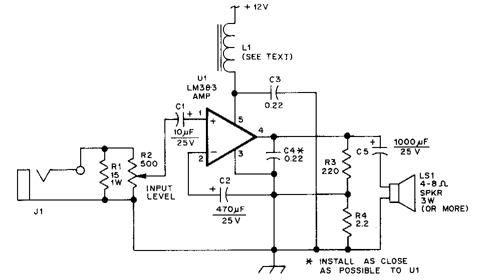
This is the ic based Audio Power Amplifier Circuit Diagram. The LM383 is an audio-power amplifier that is capable of producing up to 8 W of audio output. R1 is essentially a load resistor for the hand-held transceiver`s audio output. R2 can be composed of two fixed resistors in a 10:1 divider arrangement, but using a potentiometer makes it easy to set the amplifier`s maximum gain.

 Audio Power Amplifier Circuit Diagram

Audio Power Amplifier Circuit Diagram


When powered from a vehicle`s electrical system, the amplifier`s +12V power source requires filter L1 to eliminate alternator whine. The LM383 can ·be mounted directly on the heatsink because the mounting tab is at ground potential.


Sourced By: Streampowers
Read More

Laptop Audio Amplifier-IC LA 4440 Circuit Diagram

This is the best IC LA 4440 Laptop Audio Amplifier circuit diagram, the audio output from the laptop’s built-in loudspeakers is low. A energy amplifier is needed to obtain a high volume. This is a simple circuit to amplify the laptop’s audio output. The circuit is made around energy amplifier IC LA 4440 (IC1) along with a couple of other components. LA4440 is really a dual funnel audio energy amplifier.

Circuit diagram :
Laptop-Audio-Amplifier-IC-LA-4440
Laptop Audio Amplifier Circuit Diagram

It’s low distortion over an array of low to high wavelengths with good funnel separation. Built-in dual channels enable it for stereo system and bridge amplifier programs. In dual mode LA4440 gives 6 w per funnel as well as in bridge mode 19- watt output. It’s ripple rejection of 46 dB. The audio result can be recognized by utilizing two 6-watt loudspeakers.

Connect hooks 2, 6 and ground of IC1 towards the stereo system jack which is combined with laptops. Assemble the circuit on the general-purpose PCB and enclose inside a appropriate cabinet. The circuit works off controlled 12V power supply. It’s suggested to make use of audio input socket within the circuit board. Make use of a proper warmth-sink for LA4440.
source by
Read More

Signal Injector Circuit Diagram

This circuit is wealthy in harmonics and is good for testing amplifier circuits. to seek out a fault in an amplifier,
connect the planet clip to the 0v rail and move through each stage, beginning at the speaker. a rise in volume ought to be heard at every preceding stage. This Injector will bear the IF stages of radios and FM sound sections in TV's. to Index

Signal Injector Circuit Diagram


Read More

Audio Pre-Amplifier Circuit Diagram

Simple Audio Pre-Amplifier

This simple circuit provides good gain to too audio singnals .
Use it in main of an RF oscillators to make an RF transmitter that is very sensitive to sound

Audio Pre-Amplifier Circuit Diagram

Read More

50W audio amplifier LM3876 Circuit Diagram

LM3876 is a high performance audio power amplifier IC from National Semiconductors. The LM3876 can deliver 50watts of output power into an 8 ohm loudspeaker. LM3876 has excellent signal to noise ratio and has wide supply voltage range. Other features of LM3876 are output to ground short circuit protection, input mute function, and output over voltage protection, etc. Applications of LM3876 are component stereo, compact stereo, surround systems, self powered speakers, etc.

Circuit diagram :
50-w-audio-amplifer-circuit diagram
50W audio amplifier Circuit Diagram

The 50 watt audio amplifier  circuit shown below is designed based on the application diagram from the data sheet of LM3876. Some modifications are made on the original circuit for improving the performance. The bipolar electrolytic capacitor C7 is the input DC decoupling capacitor. R4 is the input resistance. R2 & R1 and bipolar electrolytic capacitor C5 forms a feedback circuit. C2, C1 are filter/by-pass capacitors for the positive supply rail. C4 & C3 are the filters/by-pass capacitors for the negative supply rail. The feedback resistor R2 sets the gain of the amplifier. L1 provides high impedance at high frequencies so that R7 may decouple capacitive loads. R3 is the mute resistance which allows 0.5mA to be drawn from pin8 to turn the mute function OFF. S1 is the mute switch. Resistor R6 and capacitor C8 forms a Zobel network which improves the high frequency stability of the amplifier and prevents oscillations.

Notes :
  • The LM3876 can be operated from a supply voltage range of +/-12V to +/-49V DC.
  • I recommend +/-35V DC for powering the IC.
  • LM3876 requires a proper heat sink.
  • Quiescent current of LM3876 is around 70mA

Read More

10 to 14W Class A Audio Amplifier Circuit Diagram

I have built this amplifier and it does sound good. It requires a preamp as it hasn't got much gain. It requires big heat sinks and a large transformer and a great power supply and careful wiring, but in the end it is xtremely simple and it sounds very good. The zener diode rejects any ripple coming from the power supply, But you still only want a ripple of 10mV max. The ripple reaching the input is amplified, so the zener diode gets rid of that, but whatever ripple there is will still reach the power stage.

10 to 14W Class A Audio Amplifier
Read More

Small Audio Amplifiers Using LM386 and NE5534

Many electronic projects require the use of a small audio amplifier. Be it a radio transceiver, a digital voice recorder, or an intercom, they all call for an audio amp that is small, cheap, and has enough power to provide adequate loudness to fill a room, without pretending to serve a disco! About one Watt RMS seems to be a convenient size, and this is also about the highest power that a simple amplifier fed from 12V can put into an 8 Ohm speaker. A very low saturation amplifier may go as high up as 2 Watt, but any higher power requires the use of a higher voltage power supply, lower speaker impedance, a bridge circuit, or a combination of those.

During my many years building electronic things I have needed small audio amps many times, and have pretty much standardized on a few IC solutions, first and and foremost the LM386, which is small, cheap, and very easy to use. But it does not produce high quality audio... For many applications, the advantages weigh more than the distortion and noise of this chip, so that I used it anyway. In other cases I used different chips, which perform better but need more complex circuits. Often these chips were no longer available the next time I needed a small amplifier.

When I last upgraded my computer, I replaced the old and trusty Soundblaster AWE 32 by a Soundblaster Audigy. The new card is better in many regards, but while the old one had an internal audio power amplifier, the new one doesn't! That's bad news, because I have some pretty decent speakers for the PC, which are fully passive. So, I built a little stereo amp using two LM386 chips and installed it inside the computer, fed by the 12V available internally.

But then I wasn't satisfied. The LM386 might be suitable for "communication quality" audio, which is roughly the fidelity you get over a telephone, but for music it's pretty poor! The distortion was awful. So, the day came when I decided to play a little more scientifically with small audio amps, looking for a way to get good performance with simple and inexpensive means.

I set up a test bench with a sine wave oscillator running at 1 kHz, an 8 Ohm speaker, 12V power supply, and the computer with the soundcard and Fast Fourier Transform software. One channel was connected to the oscillator together with the amplifier input, the other channel to the output and speaker. With this setup I measured the harmonic content of the audio signals. I did the tests at an output level of 0.1W, which is typical for moderately loud sound from a reasonably efficient speaker. Also, I used a music signal from a CD player to test the actual sound of each amplifier.

Circuit Project: Small Audio Amplifiers Using LM386 and NE5534

As already said above, the main attraction of the LM386 is the extreme simplicity of its application circuit. You can even eliminate R1 if the signal source is DC-grounded. If the speaker leads are long, you should add an RC snubber across the output to aid stability. Additionally, if you need higher gain (not necessary if the input is at line level), you can connect a 10uF capacitor between pins 1 and 8. That's about all there is to it.

Now the bad news: This circuit produced a very high level of distortion! The second harmonic measured just -28dB from the main output. The third harmonic was at -35dB, while the noise level was at -82dB. There were assorted high harmonics at roughly -45dB. With music, the distortion was really disturbing, and also the noise level was uncomfortably high. The power supply rejection is poor, so that some hum and other supply noise gets through. In short, this was a lousy performance!

Since I had used so many LM386s in my projects, I had several different variations. In my material box I found a slightly newer LM386N-1. So I plugged it into my test amplifier. It was even worse! The second harmonic was at -24dB, the third harmonic at -31dB, while the noise was a tad better at -84dB. Folks, that's a total harmonic distortion of almost 7%! And the 0.1W output level at which this was measured is where such a circuit is about at its best...  The distortion can be plainly seen on the oscilloscope, and a visibly distorted waveform is about the most offending thing an audio designer can ever see!

Looking through my projects, I found one where I had used a GL386 chip. This is just a 386 made by another company. I unsoldered it and put it in my test amplifier. Surprise! It was dramatically better, with the second harmonic at -45dB, and the third at -57dB! The noise floor was -84dB, just like the LM386N-1. But even this level of distortion was plainly audible when listening to music. That's roughly 0.6% THD. Some folks may consider it acceptable for music. I don't, but for communication equipment it's fine. At this point, I decided to see if I could build a better amplifier, that doesn't become too complex nor expensive.

Circuit Project: Small Audio Amplifiers Using LM386 and NE5534

This was the first attempt. A low distortion, fast slew rate, but easy to find and rather inexpensive operational amplifier, driving a simple source follower made of two small transistors. These transistors are not biased, so they work at zero quiescent current, in full class B. The only mechanism that works against crossover distortion here is the high slew rate of the OpAmp, which is able to make the distortion bursts during crossover very short. To say the truth, I didn't expect to get usable performance from this circuit, and was really surprised when it worked much better than the 386! The second harmonic was at -77dB, the third at -79dB!

Also there were many high harmonics at roughly -84dB. That means a THD of about 0.015%.  The noise floor was down at the -120dB level! The power supply rejection was excellent, with no detectable feedtrough. Playing music, this amplifier sounded really good: No audible noise, and the distortion could be heard when paying attention to it, but I doubt that the average person would detect it! Not bad, for a bias-less design!

Just to see how important the slew rate of the OpAmp is, I pulled out the NE5534 and replaced it by a humble 741, which is many times slower. The result was dramatic: The second harmonic still good at -70dB, but the third harmonic was much worse, at -48dB. Also there were many high harmonics at the same -48dB level. Given that second harmonic distortion doesn't sound bad to most people, but third harmonic does, and high harmonics are even worse, it came as no surprise that the amplifier with the 741 sounded bad.

At low volume it sounded particularly bad! So I returned to the oscillator and measurement setup, testing at lower output power, and found that while the second and third harmonics followed the output, the high harmonics stayed mostly constant! So, at very low output, the high harmonics became very strong relative to the output. All this is the effect of the slower slew rate of the 741, which makes it less effective correcting the crossover distortion of the unbiased transistors. Interestingly, the noise floor of the 741 circuit wasn't bad: -118dB.

Just for fun, I tried this circuit with a third OpAmp: The TL071, which is good, but not as good as the 5534. The results: Second harmonic at -72dB, third and the high ones at -60dB, and the noise at -120dB. It's interesting that the second harmonic is much more suppressed than the third one. That must be a balancing effect of the symmetric output stage, and the better symmetry in the TL071 compared to other OpAmps.

It's worthwhile to note that this amplifier can be simplified a lot by using a split power supply. R1, R2, C1, C2 and C4 would be eliminated! But then you need the capacitor removed from C4 to bypass the negative supply line. The positive input of the chip goes to ground, while pin 4 and the collector of Q2 go to the negative supply. The rest stays the same. If you use a +-15V supply, the available RMS output power grows to over 10 Watt! Of course, you then need larger transistors. And since larger transistors are slower, the distortion will rise somewhat. An added benefit of a split supply is that the popping noise when switching on and off is eliminated.

Circuit Project: Small Audio Amplifiers Using LM386 and NE5534

As the next experiment, I decided to get rid of the crossover distortion. For this purpose, I added a traditional adjustable bias circuit with a transistor and a trimpot. Now I also had to add a current source, because with the bias circuit there is no single point into which the OpAmp could put its drive current into both bases! I adjusted the bias for the best distortion, and this was really  a good one! The second harmonic was down right where the test oscillator delivered it, about -80dB, so I couldn't really measure it!

The third harmonic was at -84dB, and the best improvement was that the higher harmonics had simply disappeared! They were all below the noise floor, which stayed at -120dB. Actually, this noise floor seems to come from the soundcard A/D converter, so that the actual noise of this and the above amplifier may even be better! With music, this amplifier sounded perfect - clean and smooth. And I'm pretty confident that the THD is well below the limits of my measurement setup, which is 0.01%.

The quiescent current was around 10mA. When lowering it to about 3mA, the high harmonics started to rise out of the noise floor. If you want to adjust the bias for the exact best quiescent current, there is a simple trick: Lift R4 from the output, and connect it to pin 6. Now the output stage has been left outside the feedback loop, and all its distortion will show up at the output. Watching the signal on an oscilloscope, or even better on a real time spectrum analyzer (soundcard and software), adjust the trimpot to the lowest distortion level.

Have a current meter in the supply line and make sure that you don't exceed 30mA or so of quiescent current, in order to keep the small transistors cool. But most likely the best distortion will be at a current lower than that. Once the adjustment is complete, return R4 to its normal position. Now the full gain and slew rate of the operational amplifier is used to correct the small remaining cross-over distortion of the output stage, and the distortion will certainly disappear from the scope screen, from your ears, and possibly fall below the detection level of the spectrum analyzer!

This circuit can also be run from a split power supply, by exactly the same mods as for the previous circuit. And since the transistors are properly biased, there isn't any significant distortion increase when using larger transistors. Be sure to use some that have enough gain - you have only a few mA of driving available, and with a +-15V power supply and an 8 Ohm speaker, there can be almost 2A of output current! So, you need a gain of 300 at least. There are power transistors in the 4A class that provide such gain, and these are good candidates. The other option is using Darlington transistors, which far exceed the gain needed here. But they will again increase the distortion, not very much, but perhaps enough to make it audible again.
Source: Streampowers
Read More

LM1875 – POWER AMPLIFIER 20 WATT CIRCUIT dIAGRAM

LM1875 – POWER AMPLIFIER 20 WATT
The LM1875 is a monolithic power amplifier offering very low distortion and high quality performance for consumer audio applications.

The LM1875 delivers 20 watts into a 4Ω or 8Ω load on ±25V supplies. Using an 8 load and ±30V supplies, over 30 watts of power may be delivered. The amplifier is designed to operate with a minimum of external components. Device overload protection consists of both internal current limit and thermal shutdown.

The LM1875 design takes advantage of advanced circuit techniques and processing to achieve extremely low distortion levels even at high output power levels. Other outstanding features include high gain, fast slew rate and a wide power bandwidth, large output voltage swing, high current capability, and a very wide supply range. The amplifier is internally compensated and stable for gains of 10 or greater.

Features
• Up to 30 watts output power
• AVO typically 90 dB
• Low distortion: 0.015%, 1 kHz, 20 W
• Wide power bandwidth: 70 kHz
• Protection for AC and DC short circuits to ground
• Thermal protection with parole circuit
• High current capability: 4A
• Wide supply range 16V-60V
• Internal output protection diodes
• 94 dB ripple rejection
• Plastic power package TO-220
LM1875 - POWER AMPLIFIER 20 WATT, link
Read More

DCF77 Preamplifier Circuit Diagram

A popular project among microcontroller aficionados is to build a radio-controlled clock. Tiny receiver boards are available, with a pre-adjusted ferrite antenna, that receive and demodulate the DCF77 time signal broadcast from Mainf lingen in Germany. DCF77 has a range of about 1,000 miles. All the microcontroller need do is decode the signal and output the results on a display. The reception quality achieved by these ready-made boards tends to be proportional to their price.
In areas of marginal reception a higher quality receiver is needed, and a small selective preamplifier stage will usually improve the situation further. The original ferrite antenna is desoldered from the receiver module and connected to the input of the preamplifier. This input consists of a source follower (T1) which has very little damping effect on the resonant circuit. A bipolar transistor (T2) provides a gain of around 5 dB. The output signal is coupled to the antenna input of the DCF77 module via a transformer.
DCF77 Preamplifier Circuit Diagram 


DSf 77-preamplifier-circuit-diagram DCF77 Preamplifier Circuit Diagram
DCF77 Breadboard circuit
The secondary of the transformer, in conjunction with capacitors C4 and C5, forms a resonant circuit which must be adjusted so that it is centered on the carrier frequency. An oscilloscope is needed for this adjustment, and a signal generator, set to generate a 77.5 kHz sine wave, is also very useful. This signal is fed, at an amplitude of a few milli-volts, into the antenna input. With the oscilloscope connected across C4 and C5 to monitor the signal on the output resonant circuit, trimmer C5 is adjusted until maximum amplitude is observed.
It is essential that the transformer used is suitable for constructing a resonant circuit at the carrier frequency. Our proto-type used a FT50-77 core from Amidon on which we made two 57-turn windings. It is also possible to trim the resonant frequency of the circuit by using a transformer whose core can be adjusted in and out. In this case, of course, the trimmer capacitor can be dispensed with.
Source by : Streampowers
Read More

2.1 Surround Speaker System Circuit Diagram

 2.1 Surround Speaker System Circuit Diagram
 "Simple 2.1 Surround Speaker System " . Here I have used  three TDA 2030 IC for making signal amplification . Here you need a sub filter extra ( Sub filter circuit diagram link showing below ) . This project  mostly used in computer  . Part list and applications are showing below.

Part List

Component No:ValueUsage
All C1100MF Grounding 
All C2100nFGrounding
All C3100nFGrounding
All C4100MFGrounding
All C5100MFFeedback
All C6100MFAudio Coupling 
All C7220nFNoise Grounding 
All R11K
All R210K ( Not 1K )
All R322K
All R422K (Not 1K )
All RV1100KVolume Controlling 
All D1 To D2IN4007Potential Breaking
U1 To U6TDA2030Amplification

Applications

* 2.1 Surround Amplifier

* 2.1 Home Theater
Read More