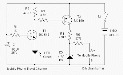
This is a Mobile Phone Travel Charger Circuit Diagram. At this point is an ideal cellular phone charger using 1.5 Volt ballpoint cells to charge mobile phone while wandering. It can refill cell phone battery three before four period in the field of spaces everyplace AC power is not on hand.
A good number of the cell phone phone batteries are rated by the side of 3.6 in opposition to/500 mA. A single create torch cell can provide 1.5 volts and 1.5 Amps current. So if four pen cells are connected serially, it wish form a battery bunch with 6 volt and 1.5 Amps current. while power is practical to the circuit through S1, transistor T1 conducts and grassy LED light.
Mobile Phone Travel Charger Circuit Diagram
Mobile Phone Travel Charger Circuit Diagram
What time T1 conducts T2 furthermore conducts since its dishonorable becomes denial. Charging current flows from the satellite dish of T1. To reduce the charging voltage to 4.7 volts, Zener diode ZD is used. The output gives 20 mA current on behalf of stupid charging. If additional current is essential for fast charging, reduce the denomination of R4 to 47 ohms so with the aim of 80 mA current desire live on hand. Points A and B are used to bond the steed with the itinerant phone. assistance as it should be pins meant for this and connect with correct polarity.
Designed by D.Mohan kumar


Thank you,
ReplyDeleteThe information you shared is very informative.