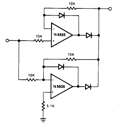
This Precision full wave Rectifier Circuit Diagram provides accurate full wave rectification. The output impedance is low for both input polarities, and the errors are small at all signal levels. Note that the output will not sink heavy current, except a small amount through the 10K resistors. Therefore, the load applied should be referenced to ground or a negative voltage. Reversal of all diode polarities will reverse the polarity of the output
Since the outputs of the amplifiers must slew through two diode drops when the input polarity changes, 741 type devices give 5% distortion at about 300 Hz.
Precision full wave Rectifier Circuit Diagram
Since the outputs of the amplifiers must slew through two diode drops when the input polarity changes, 741 type devices give 5% distortion at about 300 Hz.
Precision full wave Rectifier Circuit Diagram


0 comments:
Post a Comment