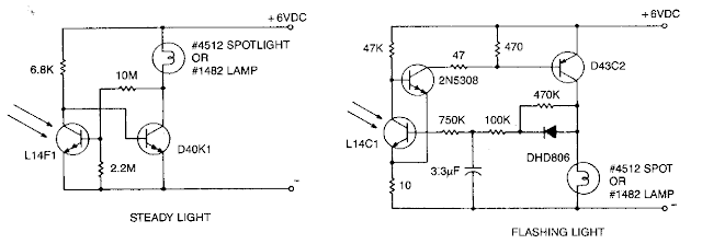
This is a Warning Light and Marker Light Circuit Diagram. A flashing light of high brightness and short duty cycle is often desired to provide maximum visibility and battery life. This necessitates using an output transistor, which can supply the cold filament surge current of the lamp while maintaining a low saturation voltage. The oscillation period and flash duration are determined in the feedback loop, while the use of a photo transistor sensor minimizes sensitivity variations.


0 comments:
Post a Comment